Click These:

Monday, December 15, 2025

How to set up OAUTH 2 via Google Cloud Console to use with a local python script


If you’re looking to set up OAuth 2.0 on Google Cloud to use with a local Python script, there are a few things you need to do. This was tricky for me initially, so for anyone who might be struggling to figure it out, here’s a quick guide to get you started.


1. Go to the Google Cloud Console and create a new project.


2. Give your project a name and click “Create”.


3. Once your project has been created, click on the “APIs & auth” menu item in the left hand sidebar.


4. In the APIs & auth menu, click on the “Credentials” sub-menu item.


5. On the Credentials page, click on the “Create new Client ID” button.


6. In the “Create Client ID” modal window, select the “Installed application” radio button and click “Configure consent screen”.


7. On the “Configure consent screen” page, fill in the “Product name” field and click “Save”.


8. Back in the “Create Client ID” modal window, select the “Other” radio button for the “Application type” field and click “Create Client ID”.


9. On the “Client ID created” page, copy down the “Client ID” and “Client secret” values. You will need these later.


10. Click on the “Download JSON” button and save the file to your computer.


11. Open the JSON file in a text editor and copy the contents into a new file called client_secrets.json in the same directory as your Python script.


12. Install the Google API Python client library by running the following command in a terminal:


pip install --upgrade google-api-python-client


13. Add the following lines of code to your Python script:
(in this example we're connecting to the calendar API)


from oauth2client.client import OAuth2WebServerFlow


flow = OAuth2WebServerFlow(client_id='YOUR_CLIENT_ID',

                           client_secret='YOUR_CLIENT_SECRET',

                           scope='https://www.googleapis.com/auth/calendar')


14. Replace YOUR_CLIENT_ID and YOUR_CLIENT_SECRET with the “Client ID” and “Client secret” values that you copied down earlier.


15. Run your Python script and follow the instructions that appear in the terminal to complete the OAuth 2.0 flow.


And that's it! Congrats, you should now have a working python script that can connect with Oauth 2!

I know it was pretty dry reading but if you liked this article feel free to share, subscribe, all that typical stuff... If you have any questions, I encourage you to ask in the comments. 

Tuesday, August 20, 2024

Automating Timestamps in OBS: A Python Script for Seamless Scene Logging

Are you looking for a way to automatically track and save timestamps for your OBS scenes during streams or recordings? Whether you're a content creator managing gaming streams, podcasts and interviews, tutorials and reviews, tarot and astrology readings, or any other type of live or recorded content, this Python script will streamline the process. No more manual logging of scene changes—this script will generate a detailed timestamp file when you stop streaming or recording.

Why Automate Scene Timestamps?

Tracking scene transitions is crucial for organizing content, especially when you review your footage or create time-based highlights. Manual tracking can be tedious, and OBS doesn’t have a built-in feature to log timestamps in a user-friendly way. That's where automation comes in.

With this Python script, timestamps are logged and saved as a text file automatically, making the post-production process much smoother. And, it even generates hashtags that are useful for astrologers or tarot readers, making the script perfect for niche content creators!

How the Script Works

This Python script integrates seamlessly with OBS, capturing when scenes change and logging their durations. When the stream or recording ends, a timestamp file is generated and saved to your desktop. Here's a breakdown of how the script works:

  1. Scene Tracking: The script captures each scene name and its duration during the stream or recording session.
  2. Hashtag Generation: The script adds pre-configured hashtags, like #tarot #astrology #allsigns #tarotreading #love #lovereading, to the timestamp file.
  3. Timestamps and Total Duration: For each scene, a starting timestamp is logged, and once the session ends, the total stream/recording time is appended at the bottom of the file.
  4. Output: The result is a well-organized text file saved to your desktop, containing a breakdown of each scene's start time and the total session duration.

The Python Script: "timestamps.py"

import os import datetime # Generate timestamp file on stop def generate_timestamp_file(mode): global scene_history, start_time # Automatically get the desktop path for the current user desktop_path = os.path.join(os.path.expanduser("~"), "Desktop") timestamp = datetime.datetime.now().strftime("%Y-%m-%d_%H-%M-%S") filename = os.path.join(desktop_path, f"timestamps_{timestamp}.txt") total_duration = time.time() - start_time total_duration_str = time.strftime("%H:%M:%S", time.gmtime(total_duration)) with open(filename, 'w') as f: # Write hashtags f.write("#tarot #astrology #allsigns #tarotreading #love #lovereading\n\n") # Calculate starting time for each scene accumulated_time = 0 for i, (scene_name, duration) in enumerate(scene_history): start_time_str = time.strftime("%H:%M:%S", time.gmtime(accumulated_time)) f.write(f"{scene_name}: {start_time_str}\n") accumulated_time += duration # Add total duration after a blank line f.write("\n") if mode == "stream": f.write(f"Total stream time: {total_duration_str}\n") else: f.write(f"Total recording time: {total_duration_str}\n") print(f"Timestamps saved to {filename}")

Setting It Up

To use this script with OBS, follow these simple steps:

  1. Save the Script: Copy the Python code and paste it into a new text file. Save the file as timestamps.py on your computer.

  2. Install Python: If you don’t have Python installed, download it from the official Python website at python.org. Make sure to check the option to "Add Python to PATH" during installation.

  3. Adding the Python Path to OBS: In OBS, go to Tools > Scripts, then click on the Python Settings tab. Browse and set the Python Install Path to the folder where Python is installed (usually something like C:\Python39 or similar). OBS requires Python 3.6 - 3.9 to run Python scripts.

  4. Add the Script to OBS: In the Scripts window of OBS, click the + button, locate your saved timestamps.py file, and load it as an active script. This will trigger the functions of the script whenever a recording or stream is started, and automate timestamp logging when you stop recording or streaming.

Why This Script Stands Out

  • Automation: No manual effort is required—once set up, the script runs in the background and logs your timestamps automatically.
  • User-Friendly: The timestamp file is saved directly to your desktop for easy access.
  • Versatile: It works for both streams and recordings, ensuring you never miss out on logging important scene transitions.

Conclusion

Whether you're livestreaming games, podcasts, tarot readings, astrology sessions, educational material, or doing live or recorded content creation of any kind, this Python script helps you keep track of your scene transitions effortlessly. With timestamps and total durations neatly organized, you can easily revisit key moments in your streams or recordings.

Integrate this automation into your OBS workflow and let the script handle the heavy lifting for you!

Saturday, August 17, 2024

How to Create a Custom On Screen Timer Script for OBS that Resets with Scene Changes

If you're a streamer or video creator, having a custom timer in OBS (Open Broadcaster Software) can be incredibly useful. Whether you're timing events, managing segments, or just keeping track of time, a custom timer script can enhance your streaming experience. In this article, we'll walk you through creating a custom timer script in Python that integrates with OBS, automatically resetting each time the scene changes.

Why Use a Custom Timer?

A custom timer allows you to:

  • Track time spent on different scenes or segments.
  • Display time in a way that fits your stream's aesthetics.
  • Have a timer that resets automatically with scene changes, keeping your stream organized.

Requirements

  • OBS Studio
  • Python installed on your system
  • Tkinter library (usually included with Python)

The Script

Here's a Python script that creates a timer popup window for OBS. The timer resets every time the scene changes and always remains on top of other windows.

import obspython as obs
import time
from threading import Thread
import tkinter as tk

# Global variables
timer_running = False
start_time = None
timer_label = None
root = None

# Function to start the timer
def start_timer():
    global timer_running, start_time
    timer_running = True
    start_time = time.time()
    update_timer()

# Function to stop the timer
def stop_timer():
    global timer_running
    timer_running = False

# Function to reset the timer
def reset_timer():
    global start_time
    start_time = time.time()

# Function to update the timer
def update_timer():
    if timer_running:
        elapsed_time = time.time() - start_time
        hours, rem = divmod(elapsed_time, 3600)
        minutes, seconds = divmod(rem, 60)
        timer_label.config(text="{:02}:{:02}:{:02}".format(int(hours)\
        , int(minutes), int(seconds)))
        root.after(1000, update_timer)

# OBS callback when the scene changes
def on_event(event):
    if event == obs.OBS_FRONTEND_EVENT_SCENE_CHANGED:
        reset_timer()

# Function to create the timer window
def create_timer_window():
    global root, timer_label
    root = tk.Tk()
    root.title("OBS Timer")

    # Set the timer window to always stay on top
    root.attributes("-topmost", True)

    # Set window size
    window_width = 280
    window_height = 80

    # Set the window size and position
    screen_width = root.winfo_screenwidth()
    screen_height = root.winfo_screenheight()
    x = screen_width - window_width - 10
    y = screen_height - window_height - 85

    root.geometry(f"{window_width}x{window_height}+{x}+{y}")

    # Set the background color to very dark grey
    root.configure(bg="#1a1a1a")

    timer_label = tk.Label(root, text="00:00:00", font=("Pricedown Bl", 48)\
    , fg="purple", bg="#1a1a1a")
    timer_label.pack()

    start_timer()

    root.mainloop()

# OBS script description
def script_description():
    return "Timer popup that resets on scene change, always visible on top \
    of other windows, and positioned in the lower right corner."

# OBS script load
def script_load(settings):
    obs.obs_frontend_add_event_callback(on_event)
    timer_thread = Thread(target=create_timer_window)
    timer_thread.start()

# OBS script unload
def script_unload():
    stop_timer()
    if root:
        root.quit()


 Instructions for Loading the Script into OBS

  1. Save the Script: Copy the provided script and save it as a .py file on your computer.

  2. Open OBS Studio: Launch OBS Studio on your system.

  3. Add the Script:

    • Go to Tools in the top menu.
    • Select Scripts from the dropdown.
    • In the Scripts dialog, click the + button to add a new script.
    • Browse to the location of your saved Python script and select it.
  4. Run the Script: The script will now start running, and you should see a timer window appear in the lower right corner of your screen. This timer will reset every time you switch scenes in OBS.

With this custom timer script, you can keep track of time more effectively during your streams or recordings. The integration with OBS ensures that your timer resets with each scene change, making it a valuable tool for managing live content. Enjoy your enhanced streaming setup!


Feel free to adjust or expand upon this draft as needed!

Tuesday, June 2, 2015

The Original Kurt At Work

I used to work as a sign shaker at a certain cell phone carrier location in northern California. The job sucked until I had music... from that point on the job was pretty awesome.

I made this video shortly after realizing how awesome my job was, mostly because I wanted people to know what I was hearing when I was doing what I did, because I assumed that most people thought my movements were just uncoordinated random flailing.

When I went to name this video, 'Kurt At Work' popped into my head, and thus the name of this blog and many other projects was also created.

Shortly after posting the video to reddit, it gained about 40,000 views within a matter of days. some people thought i got paid a bunch of money to make the video as some sort of corporate attempt at a viral video campaign... but nope. I wish that had been the case. I made it myself just for the heck of it.

thanks for reading. subscribe and comment. suggestions and feedback appreciated.


Wednesday, December 24, 2014

Wireless Midi Controller - Prototype 2

I wrote on here a while ago about wanting to turn a tv remote into a MIDI controller using an arduino and an Infra-red receiver component...

i came up with a new idea... how about making a midi controller out of a tv remote... but making the receiver really badass looking too...

so, i decided i would create an all new version of the project...
i wanted it to have alot of lights in the receiver so that there is some visual feedback for when buttons are pressed, as well as giving an indication of the values of midi parameters...

i rigged up some digital shift registers in a daisy chain and hooked the outputs up to RGB LEDs, and installed a library written by Elco Jacobs that allows me to pulse width modulate however many outputs i need through the shift registers... so, in laymans terms, i could control however many lights i need individually, and mix any color and brightness...

you can find more info about the ShiftPWM library here

... the thought of having a really trippy looking lit up pyramid that helps me make music seemed pretty appealing to me...so i set to work on it...

at first i made the design out of a Krave cereal box... i made a basic shield for the project and starting soldering together the shift registers... i got the whole thing wired up with 2 RGB LEDs (because thats all that will fit on one shift register alone) and when i uploaded the code, the lights and the shift registers were not working right... all the lights would light up whenever just one was supposed to...

i kept going over the code again and again, looking for problems with the soldering... but just couldn't find anything wrong... eventually i decided to go without having a whole bunch of tri color LEDs, and that it would be simpler to just do 2 RGB LEDs using the arduino's 6 digital PWM outputs...

...but then i thought, what if i use the arduino mega that has been sitting on my shelf doing nothing?... it has 12 digital PWM outputs built in already, and i started finding code online for making other digital pins produce pwm...i could get up to about 54 digital pwm outputs from the mega, and maybe by using the anolog outputs too... i could get another 16...

still though, thats only 70 outputs and thats only enough to control 23 RGB LEDs at the most...

i ended up opting to go the simpler route of just doing the two RGB LEDs with the arduino uno's built in digital PWM... just to save time...

i installed this into the cardboard pyramid i had made and once i had the arduino, the IR receiver and the RGB LEDS in place, i put a cardboard stencil i had made on the outside and taped a layer of paper around it tightly, creating a white minimalist pyramid...

i started coding it to light up the way i wanted it to, and when i got it working and ready to start programming the IR signals and midi functionality, i realized that the remote i had bought was not ideal... and that if i wrote code around the current remote i would probably just have to rewrite alot of code later on...

so far its only functional as a light fixture in the corner of my room... but i have big plans for this pyramid... stay tuned to see how it turns out...

thanks for reading. subscribe and comment please. suggestions and feedback appreciated.

Saturday, May 10, 2014

Garden Watering System Using Arduino and 595 Shift Registers

hey everyone, i just wanted to write about a project i've been working on recently...

a while ago, I was inspired by the 'Garden Arduino' project i found on Make.com and Instructables.com

http://www.instructables.com/id/Garduino-Gardening-Arduino/

http://makezine.com/projects/make-18/garduino-geek-gardening/

upon reading about this project, i quickly set to building it... at first i didn't have a water pump to hook up to the circuit, so i plugged in the nearest thing i could find instead... i ended up having a plant that was controlling my lava lamp. whenever it needed water, it would kick on the lamp... i would water the plant, the lava lamp would turn off until the plant needed water again. this alone was pretty cool...

eventually i got a small water pump, enough to deliver a little trickle of water to a plant, i think i pulled it out of a small garden fountain type thing... i replaced my lava lamp with a water pump and VOILA! self watering plant.

at this point, my plant started doing pretty nicely, but family members were concerned about the high voltage electrical equipment being around water like that... (the circuit for the project requires relays that control 120 volt AC current - potentially very dangerous when mixed with water) anyway, long story short, i decided to take apart the project due to the concerns that were raised by those around me. everyone slept more soundly knowing that there was less potential for some sort of electrical fire or something caused by a water spill or a bare wire, etc...

even though i ended up taking it apart, i never put the project completely out of my mind... i thought to myself that i'd like to build that project again, except even BETTER...

i thought about how things were with that project and how i might do it differently... for instance...

-using a water pump that actually has some decent pressure...

-detecting the moisture level for the soil separately  for each plant and then be able to route water to exactly the plant that needs it...

-LCD display for showing sensor readings and other info.

-some way to interact with the garden controller after uploading, so that you can change variables manually such as watering time, minimum soil moisture level that triggers watering, how many plants are hooked up to controller, which plants are actively being watered or are suspended from watering for maintenance or other reasons, etc...

-use 9volt or 12 volt solenoids and pump so that there is much less danger of between the water and the electrical circuits.

...i put this project on the backburner for quite a while, but for the last few months i had been researching and making strategic purchases with this project in mind... acquiring some 595 shift registers for the specific purpose of expanding my digital outputs for controlling relays that would eventually be hooked up to solenoids and a water pump...

i decided to use half of the shift register outputs for controlling the relay bank (pump, solenoids), and the other half for controlling which plant soil moisture sensor is active.

so far i've gotten a better pump, some solenoids, water lines, water line connectors and adapters, duct tape, electrical wire, shift registers, analog multiplexers, LEDs, resistors, some galvanized nails, an LCD screen,  9v and 12v DC adapters, electrical tape, solder...

i'm starting to get things arranged and things are finally coming together really nicely. in my next post i'll write up how i'm building it, show some schematics and the code i wrote to get it all working, and offer ideas for other things i might be able to add to it, or other ways to enhance it.

thanks for reading. subscribe and comment please. suggestions and feedback appreciated.

Friday, October 11, 2013

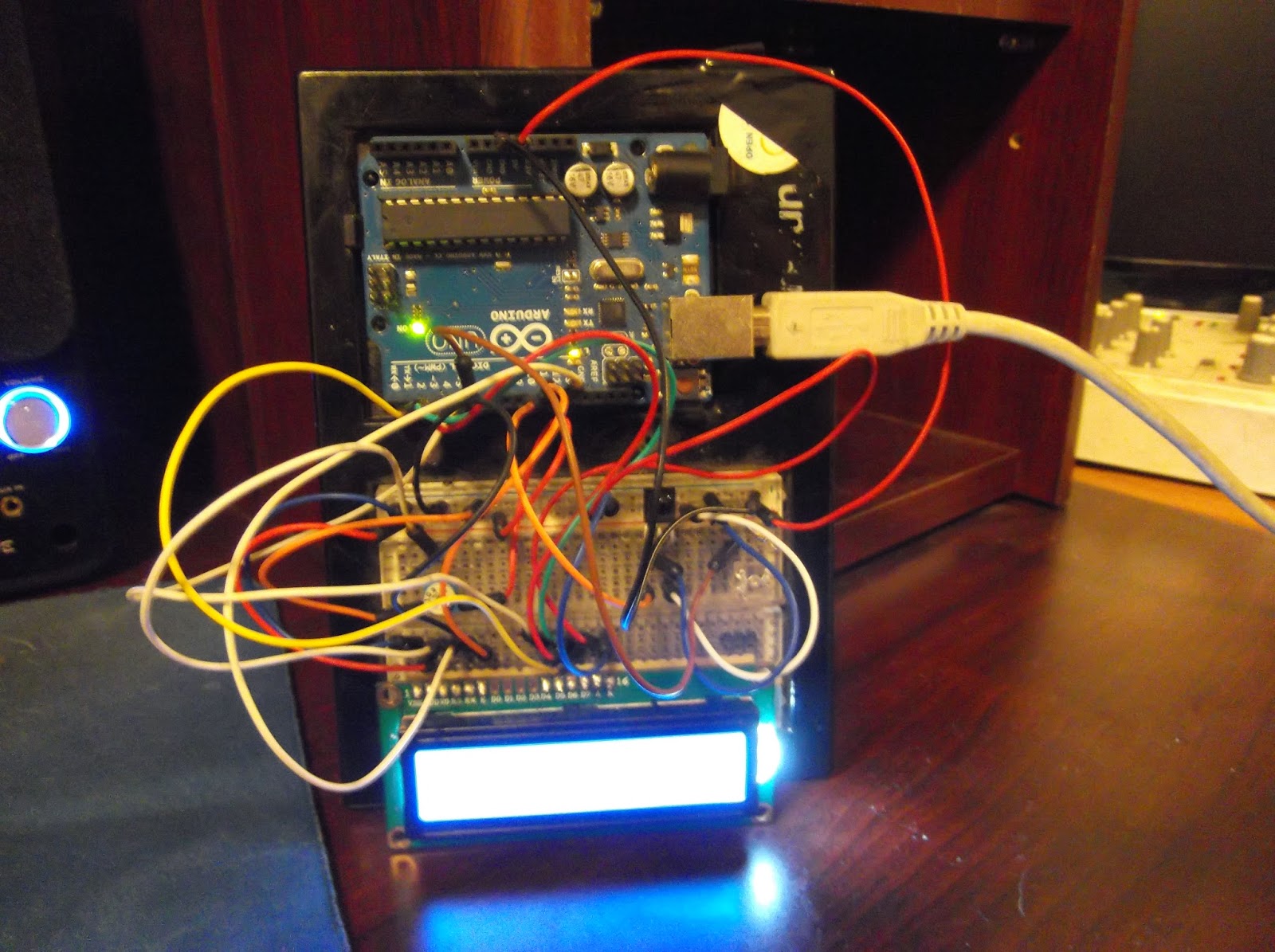
IR Receiver + LCD + LED + Arduino

Here is the groundwork for being able to take signals from any IR remote control (TV remote, VCR remote, DVD remote, SAT remote, etc)... and then after that, the idea is that you'll think of something to do with those buttons presses, and then write code that does what you want it to do...

it decodes the IR signals, and displays them on an LCD screen... as well as blinking an LED to let you know that the signal is received...

Here's a link to the Arduino code:

and the circuit itself is very simple.

just hook up the Infrared receiver component to 5v and ground, with the output signal going to digital pin 10 on the arduino.

connect the high power LED (or any other LED for that matter) to the arduino through digital pin 6, connect a 330 ohm resistor between the LED and ground.

as far as the LCD goes, just hook it up in the following sequence:
LCD RS - digital pin 12
LCD Enable - digital pin 11
LCD D4 - digital pin 5
LCD D5 - digital pin 4
LCD D6 - digital pin 3
LCD D7 - digital pin 2
LCD R/W - ground

last but not least, take a 10k ohm potentiometer and hook up the ends to 5v and ground, and then connect the wiper (the middle pin usually) to the LCD VO pin on the LCD display... this will control the contrast of the LCD, which is actually surprisingly very sensitive and needs to be dialed in just right to be able to see anything at all on the display.

once you connect everything together, upload the code, and get it going for the first time, you'll see the letters start to appear as you slowly turn the potentiometer dial... once you find the sweet spot, just leave the dial alone and don't touch it or breath on it or anything...

at this point, you should be able to see the words 'hello, world!' and if you happen to have a tv remote or any other sort of infra red remote control, point it at the receiver and push a button... you should see the hexadecimal value of the IR code that the remote is sending... you can write this value down and use it later on when you decide to program your arduino to do your bidding at the push of a button...

there are alot of possibilities for something like this... alot of different uses for being able to control something remotely... especially an arduino... think of all the things you could do with this...

as for me, this is just another step on my way to creating an awesome midi controller...

thanks for reading. subscribe and comment please. suggestions and feedback appreciated.

Wednesday, October 24, 2012

Universal TV remote + Arduino = Wireless Midi Controller

So, i remember writing a while back about a project i wanted to do that involved turning a tv remote into a wireless midi controller, so i can control my computers audio programs from across the room during production and from across a stage during performance.

So far, i've been able to write up some code that looks for certain signals from the TV remote and then spits out midi data to my computer through a USB serial connection.

I've also made a small 'shield' that is easily installed into the arduino that has an Infrared sensor on it to detect the IR signals from the remote, and it also has a tri color LED on it, so that i can see that my button presses are being registered by the device.

the picture at the top is the receiver and LED shield that i made. The picture at the right is what it looks like when its hooked up to the arduino. basically, it is a receiver of the TV remotes signal, and it translates the signal into something the computer can work with.


If you want to use the code i've written, or enhance it in any way, feel free to do so.

to get started you will need to have an arduino ready, download the IR library written be Ken Shirriff
at this link and upload the following code to your arduino. (sorry the code is so long, i could probably make it alot more efficient by writing in some new functions)
here is a link to the arduino code for the project
You'll also need a program to translate from Serial to midi... like this one... http://spikenzielabs.com/SpikenzieLabs/Serial_MIDI.html

also, depending on which tv remote you have, you might need to reprogram in your own IR codes and make adjustments to the way the code runs depending on how your tv remote sends its signals... my tv remote would send two alternating IR signals for each button pressed... yours might work differently, meaning you'll need to make changes to the code...

after some tinkering, you should be at the point where it all works and you can sit back and enjoy your own open source, fully programmable universal tv remote midi controller...

thanks for reading. subscribe and comment please. suggestions and feedback appreciated.

Friday, October 19, 2012

The Return of Kurt At Work

Hey, i just wanted to write and let everyone know i'm planning on writing more updates to this blog of music, electronics, art, and other projects that i call "Kurt At Work"...

The reason i haven't been writing and adding to 'Kurt At Work' is because i've been working alot trying to earn a living. i guess when Kurt is LITERALLY at work, 'Kurt At Work' doesn't really get worked on that much, even though Kurt is in fact working...

long story short, i'm here... i'm still alive... and i'm still planning on doing something awesome, and then doing even more 'something awesome' after that. I'm going to document it, and write about it here. you've been warned.

that is all.

Wednesday, December 28, 2011

Computer Drawing Time Lapse Video 2

I had an idea and i just went with it... the medium is pencil and sharpies... the canvas is my computer...

Here is a new video of me adding new art to my computer.

its just a short time lapse of me adding the hindu god Shiva riding huge tsunami wave on a surfboard right into what appears to be some city that vaguely resembles San Francisco as the earth crumbles and cracks in the foreground...

the music in the video was made by my friend Lake Monster...

thanks for reading. subscribe and comment please. suggestions and feedback appreciated.

Tuesday, December 27, 2011

computer drawing time lapse video

check this out...

arduino christmas project: GIFTUINO

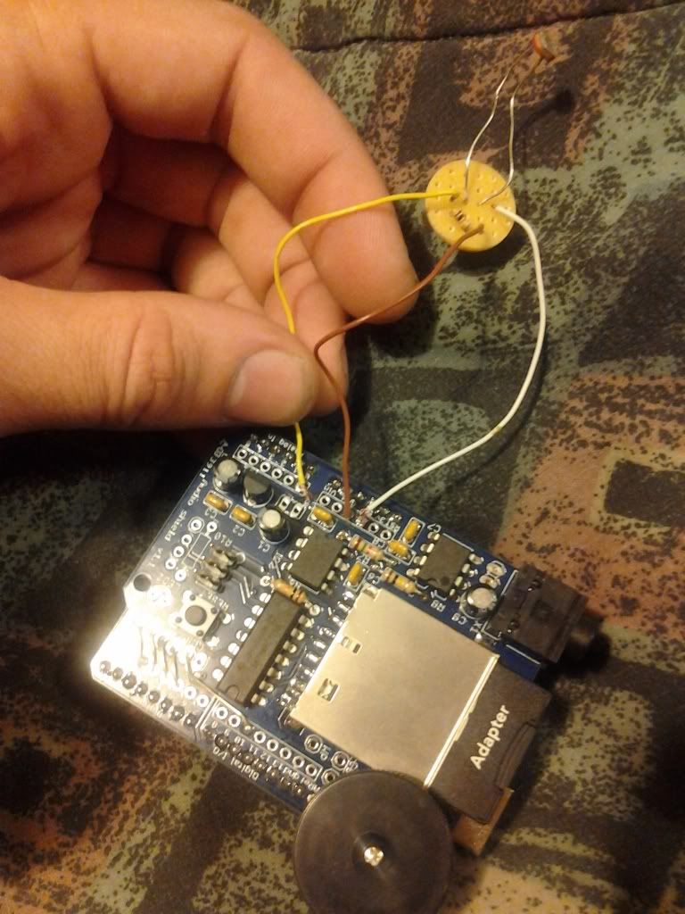
I recently made this as a christmas present for a friend. it's a gift that plays audio files when it opened. I made it with an arduino, a wav audio shield, a photoresistor, a 10k ohm resistor, some wire, solder, and a little bit of pcb.

you can pick up a wav audio shield online fairly easily... order this handy shield, solder it together and the rest of this project is super simple...

You put the audio files onto an sd card as .wav files, and then you put the sd card into the wav shield. You can either download wav files or you can create your own with your favorite digital audio workstation type program.
the arduino runs code that detects the voltage from the light sensor, and based on that reading, turns the audio on and off.

The end result: a gift that says or plays whatever you want it to when its opened, and you can stop the audio and skip to the next track by closing the gift.

Below is a simple schematic that show how to build this.
you should only need 3 wires to set up the light detection.

in the pictures above, i have a white wire going to 5 volts, the brown wire going to ground, and the yellow wire going to analog input 0.

i have drawn it as red, black, and green in the diagram to the right.

Here is the code for the arduino sketch.

once you get everything wired up, have your own audio loaded on the SD card and upload the code to your arduino, you should have a very personalized gift to give. this is perfect for holidays, birthdays, special events, jokes, pranks, and sincere messages of thanks...

there are also plenty of outputs left on the arduino for controlling lightsor any other sort of bells and whistles you'd like to add to this project...

you can see it in action in the video below...

thanks for reading. subscribe and comment please. suggestions and feedback appreciated.

Monday, December 26, 2011

new watercolors

I just got a set of watercolors for christmas. this is the first thing I've made with it. it's not quite done yet, I'm going to finish it later on.


Friday, December 23, 2011

Computer art

I've been adding art here and there to my computer for a while now. I haven't finished it yet but I'm getting there...
it's mostly done in colored markers, but it has some pencil and colored pencil as well. I might add some paint to it later on...


Universal IR Remote + Arduino: Obtaining IR Receiver Codes

I recently thought it would be cool to take a universal remote control made for a tv/dvd/vcr/etc... and turn it into a midi controller for my computer, using an arduino, the aforementioned universal remote control, and an infrared receiver. 


all you need to do to set it up is get an infrared receiver and connect the infrared receivers pins to the arduino. put pin 1 (the ir receivers output) to digital input 11, connect pin 2 into to ground, and connect pin 3 to 5 volt current on the arduino.


Next you are going to need to find a TV remote, or DVD remote, a universal remote, or some kind of remote... any kind will work. 


Once you've found one, you should download and install the IRremote library to your arduino's libraries folder. here is a link to download the zip folder of the IRremote library


http://www.arcfn.com/2010/01/using-arbitrary-remotes-with-arduino.html


and here is a link to the blog of the person who created that library for arduino.
http://www.arcfn.com/2009/08/multi-protocol-infrared-remote-library.html


anyway,you just download the zip file and unpack it to the arduino/hardware/libraries folder... 


once you have it installed and see it in the arduino programs libaries directory, you are ready to use the library in your code.

first off, you'll want to open up the example .pde file called IRrecvDemo

once you have this open, it should look like this.

---------------------------------------------------------------------------------------

/*
 * IRremote: IRrecvDemo - demonstrates receiving IR codes with IRrecv
 * An IR detector/demodulator must be connected to the input RECV_PIN.
 * Version 0.1 July, 2009
 * Copyright 2009 Ken Shirriff
 * http://arcfn.com
 */


#include <IRremote.h>


int RECV_PIN = 11;


IRrecv irrecv(RECV_PIN);


decode_results results;


void setup()
{
  Serial.begin(9600);
  irrecv.enableIRIn(); // Start the receiver
}


void loop() {
  if (irrecv.decode(&results)) {
    Serial.println(results.value, HEX);
    irrecv.resume(); // Receive the next value
  }
}


--------------------------------------------------------------------------------------------


upload the IRrecvDemo code to your arduino board, and open the serial monitor once its done uploading...
with the serial monitor open, and the IR receiver connected to the arduino... you should be able to get the IR signal codes from the remote control now... point your remote at the IR receiver, and push some buttons... You should start to see different numbers appear in the serial monitor.


you can write these numbers down, and create code for your arduino that will enable you to make it do something when it detects you've pressed a button on the remote. you can code the arduino to do anything you want... You can make it so that when you push a button, a motor turns on/speeds up/slows down, or make something turn on and off, or control a machine or robot, or send commands to your computer, or whatever else you can imagine it doing... you can pretty much program the remote to do any damn thing you can imagine...

i imagined using it as a MIDI controller to use with my audio programs on my computer...  so thats what i'm doing. so far, i've programmed only 1 button on the controller to send a MIDI signal... the power button. I will eventually write code that turns the whole remote into a very versatile music controller.


Friday, December 16, 2011

Kurt At Work

my name is kurt. I'm always working on something. this is a blog for documenting my work.
for starters, you can check out all the different music i have up online around the internet...
https://on.soundcloud.com/Guew8mzWrntHNy9z9